Follow the steps below to perform the Wenner Four-Electrode method using the MiniSting™.
• For more background on the Wenner Method & ASTM G57, visit this article.
• If you want to learn how to perform this method using the SuperSting™, visit this article.
Setup your MiniSting™ to perform the Wenner Four Electrode Method:
1. Make sure you use an isolated battery to power your MiniSting™ if you are using an external battery. You can power up your MiniSting™ with the internal battery as well.
2. Turn on your MiniSting™ and push the MEN button when you see the main menu (See Figure 1 below).
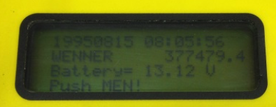
Figure 1: The MiniSting™ main menu. The main menu will show the battery's voltage.
3. Press the number 1 on the keypad to get to Menu 1 (See Figure 2).
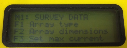
Figure 2: Menu 1 on the MiniSting™.
4. Next, press the F1 key and select the array type (a.k.a the electrode configuration) you are going to use. Press the + or - keys on the keypad to select from the supported configurations. When the configuration you want to use is displayed on the screen, press the MEN key to confirm and return to the main menu.
Note: The chosen configuration will now remain in effect until changed. When choosing a configuration, select any array EXCEPT the USER MODE—which is no longer supported.
5. Press the F3 key and use the + key to select 500 (mA). It's always best to start with the maximum current.
Note: If the MiniSting™ cannot send out the requested current because of local soil/geological conditions, it will automatically switch down to a lower current.
6. Press the MEN key to return to the main menu. Next, press the 2 key on the keypad to go to menu 2.
7. On menu 2, press F1 and use the + or - key to select the number of cycles to be stacked (we recommend 2 cycles). Press MEN to confirm and get back to menu 2.
8. Press F2 and use the + or - key to select a suitable threshold for the error tolerance (2% is a recommended value for most surveys). Press MEN to confirm and get back to menu 2.
Note: If the standard deviation of the measurement falls below the value during the stacking, the measurement is automatically interrupted and the reading is stored in the internal memory.
9. Press F3 followed by F1 to select your desired units of measure (feet or meters).
10. Press F2 to select 3.6 seconds for the measurement time (this is recommended for the majority of conditions). Press MEN to confirm and return to menu 2.
11. If you want, you can set the date and time. Press the 4 key on the keypad to go to menu 4. Press F1 to set the date and time.
12. Make sure that automatic measurement mode is turned off (This feature is no longer supported). To turn off, press the 6 key on the keypad to go to menu 6. Press F1 and then set the mode to OFF by pressing the + key. Press the MEN key to confirm and got back to menu 6.
13. Press the MEN key followed by pressing 1 on the keypad to the to return to the main menu
14. Press F2 to enter in a different a-spacing. In Figure 3 below, the last value is 1m.
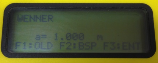
Figure 3: On this screen, you can change the a-spacing.
15. Press F2 again and then enter 2.5 (as seen in Figure 4 below). Press F3 to enter
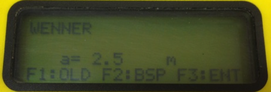
Figure 4: On this screen, continue to edit the a-spacing.
16. Go to Menu 1 (M1) and press F2 to enter electrode distances. When the distances are entered by pressing F3, the display is automatically changed back to menu 1.
Now that you have completed the setup for your MiniSting™, you are now ready to start measuring.

Figure 5: The Wenner array geometry
A or C1 = Positive current
B or C2 = Negative current
M or P1 = Positive potential
N or P2 = Negative potential
Note: Geophysics will use ABMN terms. Electrical engineers will use C1, C2, P1, and P2 terms. The a-spacing is the distance between any one of the electrodes above—like the distance between C1 and P1 (or A and M). Other arrays have different geometry and terms (please see the full MiniSting™ manual for more).
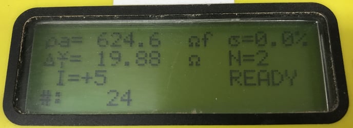
17. Press the MEA key to start your measurement cycle. Measured data will be displayed on the screen and also automatically be stored in the memory as well. This can be downloaded to a computer using the Administrator software as needed. To summarize the screenshot below: the system was previously set to the units of feet and a-spacing was entered. This reading shows 624.6 ohm-ft, with 0.0% standard deviation error for two readings. The normalized resistance V/I is 19.88 ohms, injected current was 5mA and this is the 24th reading stored in memory. The system is now ready for another reading as well.
18. Check the displayed errors to see if it is 2% or less (recommended). If not, you may want to repeat the measurement or check the electrode contact for loose or very dry electrodes. About 500ml of saltwater poured at each stake will vastly improve signal quality. Freshwater can also be used to slightly less effect. Make sure the output current (Menu 1 > F3) is set to the maximum value. An external battery will produce a stronger signal.
19. After the first reading is taken, go to step 13 above to change the electrode distances and start a new measurement.
Common Troubleshooting Issues Page is here
