Note: This article uses a 112 electrode setup as an example. You can run any number of multiple SwitchBox's with small modifications to these procedures.
Using Two SwitchBoxes:
First, Program Your SwitchBoxes:
When programming, only plug in one SwitchBox 56™ at a time into the SuperSting™. Plug in SwitchBox 56 #1 and program it to run electrodes 1-56. Run a relay test to check this box before moving on to SwitchBox 56 #2. If your test is successful, unplug SwitchBox #1 and move on to SwitchBox #2.
Use the following steps to program SwitchBox #2 to run electrodes 57-112:
Plug in SwitchBox#2 and turn the SuperSting™ on. From the Main Menu, press the following:
- Test Menu (3)
- Program Address (5)
- Address = 57
- Serial Number = 1
- Press F3
- Press Period (.) to confirm. Then, set the remaining values.
- Test Menu (3)
- Program Address (5)
- Address=85
- Serial Number =2
- Press F3
- Press Period (.) to confirm
Run a relay test to confirm that you have programmed SwitchBox #2 to run 57-112.
Tip:
Use white tape and a marker to label that SwitchBox# 1 handles electrodes 1-56. Label that SwitchBox #2 is 57-112.
Next, Setup Your Equipment:
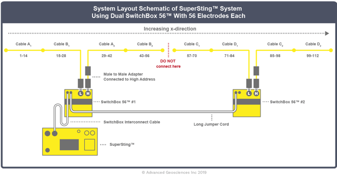
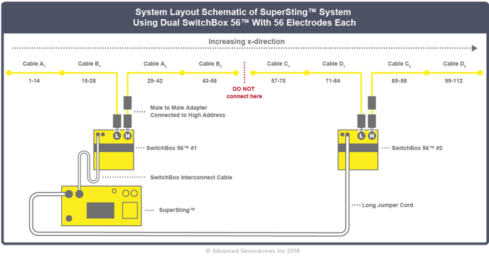
When using passive cables, it is possible to perform a survey with two SwitchBoxes, as long as both switch boxes are entered into the SuperSting. The SuperSting can be placed by either SwitchBox and is connected to the furthest SwitchBox by a long extension cable.
OR AN ALTERNATIVE SETUP:
Warning: There is no connecting cable between electrodes 56 and 57. Do not attempt to connect electrode 56 to electrodes 57, since it will cause all data from electrodes 29 to 84 to be incorrect.
Once your setup is complete, run another relay test—this time from 1-112 to make sure everything is set up correctly.
It is important that the two SwitchBoxes must be programmed with different address numbers. Just entering the total number of switches will result in an error. So SwitchBox 56 #1 is programmed with addresses 1-56 and SwitchBox 56 #2 is programmed with addresses 57-112.
Tip: Keeping track of the cable connections before performing the survey prevents erroneous data. An error connecting the cables to the low and high side of the switch box could result in unreadable, unrecoverable data. AGI recommends making a diagram of cable positions for each roll. Cover the factory labels with white electrical tape and use a marker to label the address numbers (57-112 in the example above).
In the layout example above, there is no electrical difference between cable sections 1-28 and 57-84, or between cable sections 29-56 and 85-112, making them interchangeable. However, cable section 1-28 is different from cable section 29-56, for example, so they are not interchangeable.
The multi-electrode cables have the electrode address marked by each electrode take-out. Depending on how the cables were originally purchased, the address numbers may vary. If the SwitchBox 56 #2 in the example above originally was purchased as a 56-electrode system, the cable sections 57-84 and 85-112 above might be marked with addresses 1-28 and 29-56.