To learn how to create a Command File using the SuperSting Administrator, view this article.
Creating a Command File in EarthImager™ 2D:
1. Open EarthImager 2D and select the Tools button from the menu on the top
2. In the menu choose Command Creator 2D
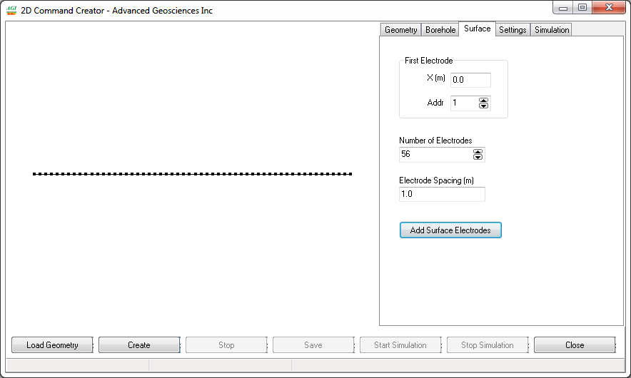
3. To set up electrode geometry, choose the Surface or Borehole Tab on the menu depending on your survey type.
For surface electrode geometry:
- Enter first electrode address number and X(m) coordinate value (This should almost always be 1)
- Enter the number of electrodes (56 shown below)
- Enter Electrode spacing (1) . Using 1 allows the Scaling Factor function on the SuperSting menus to scale up or down to any spacing that will fit your cables,
- Click “Add Surface Electrodes” to create surface electrode geometry (56 total example is below). A line of Surface Electrodes will now be plotted
For borehole electrode geometry:
- Add a borehole
- Enter the top electrode address
- Enter the top electrode X(m) coordinate
- Enter the top electrode Z(m) coordinate
- Enter the number of electrodes
- Enter electrode distance
- Add to create the borehole electrode geometry
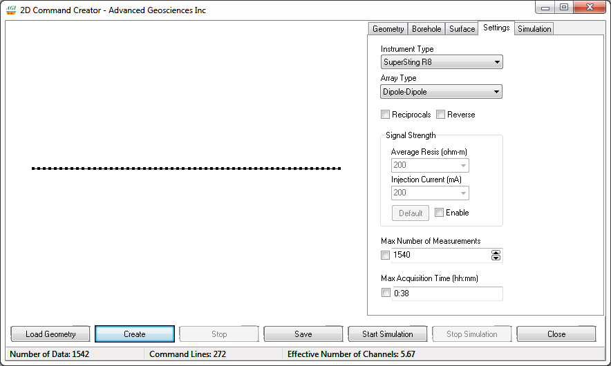
4. Choose the Setting Tab and set the instrument type, array type, and other settings:
- Choose SuperSting R8, R1 or Sting R1 from the Product Type drop down menu.
- Choose an array from the Array Type drop down menu.
- If you're creating a reciprocal measurement, select the Reciprocal box. These are done for cable/connector trouble shooting, QC and better noise estimates at the expense of run time.
- If you're doing reverse measurements, select the Reverse box. Reverse commands will run slightly faster during roll-along type surveys only.
- Choose signal strength values if you want any restrictions for creating the commands with average resistivity and current values. This should be left unchecked in most cases as these values are usually not known ahead of time.
- Choose the maximum number of measurements or maximum acquisition time if you want any restrictions for creating the command file. This will make the command file sparser.
5. Choose Create button for creating the commands. Dipole-Dipole is shown below
6. Click the Save button for saving the command file and choose a file name of 8 characters or less using standard letters and numbers. This will save with the CMD file extension which is compatible with SuperSting Administrator for PC. If you wish to transfer this file to the Android App, please change the file name as follows name.cmd.txt. You may need to change your Folder Options in Windows to enable the show file extensions option.
7. (Optional) Choose Simulation and Start Tab if you want to simulate how the measurements will be performed and how long they will take for given measurements settings set on the SuperSting (none of these simulation settings are saved in the file - all measurement settings are made on the instrument itself):
- You can change the simulation speed and symbol size
- You can choose forward or reverse simulation direction
- You can enter the command line number and make manual stepping simulations
- You can also load & simulate any previously created command file
- You can also choose different Survey Time estimation parameters to simulate survey times
Creating a Command File in EarthImager™ 3D:
1. Open EarthImager 3D and select the Tools button from the menu on the top
2. In the menu choose 3D Command Creator
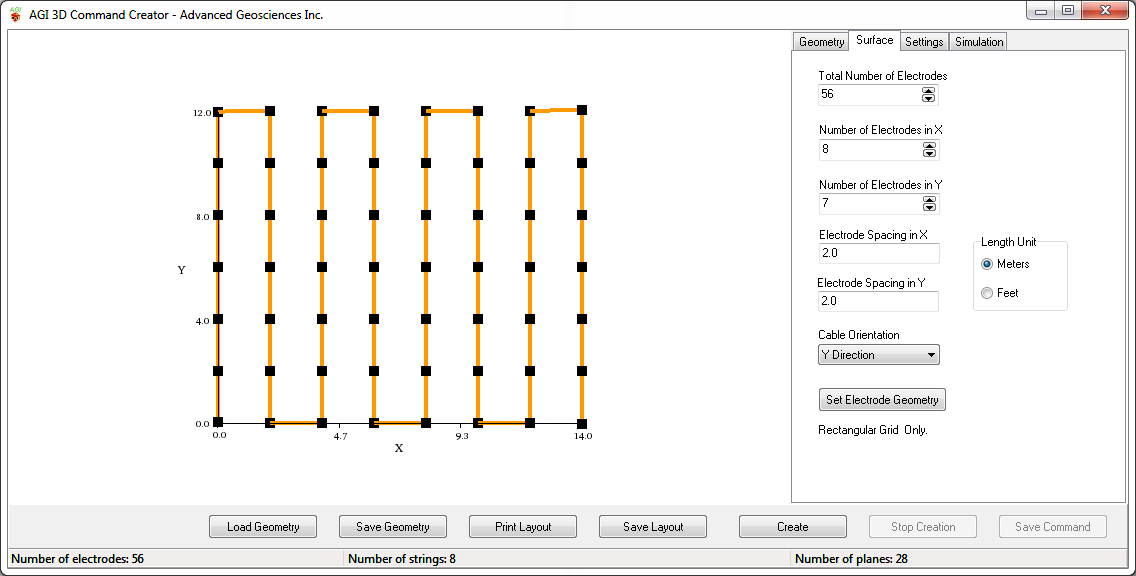
3. To set up electrode geometry, choose Surface Tab on the menu:
- Choose what unit of length you want to use (meters or feet) in Length Unit
- Enter the total number of electrodes
- Enter the number of electrodes in X direction
- Enter the number of electrodes in Y direction
- Enter the electrode spacing in X direction
- Enter the electrode spacing in Y direction
- Choose Cable Orientation in X or Y direction
- Click the Set Electrode Geometry button to create a rectangular grid of surface electrodes
- Click Save Layout and/or print the layout so that you have an image of the electrode geometry needed at the field site. There can be no deviation from this exact order and spacing. Some electrodes can be skipped in the Skip Electrode list on the SuperSting menus, but geometry is preset.
NOTE: Scaling Factor on the SuperSting menus will always be 1 for true 3D command files. These command files must
4. Choose the Setting Tab and set the instrument type, array type, and other settings:
- Choose an array from the Array Type menu. Radial Dipole-Dipole is suggested for most all 3D command file applications for optimal resolution. If the site is very noisy, the dipole-gradient is best.
- Choose SuperSting R8, R1 or Sting R1 from the Product Type drop down menu.
- If you're creating a reciprocal measurement, select the Reciprocal box. These are done for cable/connector trouble shooting, QC and better noise estimates at the expense of run time.
- Choose signal strength values if you want restrictions for creating the commands with average resistivity and current values. This should be left unchecked in most cases as these values are usually not known ahead of time.
- Choose the maximum number of measurements or maximum acquisition time if you want any restrictions for creating the command file. This will make the command file sparser.
- Choose No Cross-String Data if you want to collect spares 2D data only.
5. Choose Create button for creating the commands.
6. Click the Save button for saving the command file and choose a file name of 8 characters or less using standard letters and numbers. This will save with the CMD file extension which is compatible with SuperSting Administrator for PC. If you wish to transfer this file to the Android App, please change the file name as follows name.cmd.txt. You may need to change your Folder Options in Windows to enable the show file extensions option.
7. (Optional) Choose Simulation and Start Tab if you want to simulate how the measurements will be performed and how long they will take for given measurements settings set on the SuperSting (none of these simulation settings are saved in the file - all measurement settings are made on the instrument itself):
- You can change the simulation speed and symbol size
- You can choose forward or reverse simulation direction
- You can enter the command line number and make manual stepping simulations
- You can also load & simulate any previously created command file
- You can also choose different Survey Time estimation parameters to simulate survey times