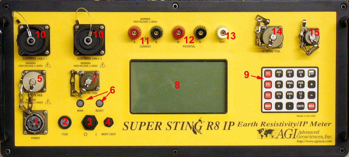
1. Power connector.
2. Fuse holder (20A only with 1A and 2.5A inside the machine).
3. O/I (OFF/ON).
4. Night light, used to illuminate the display during poor light conditions.
5. Connector for optional external transmitter (only on SuperSting R8/IP).
6. Indicator light for main and booster mode (on SuperSting R1 there is no indicator light for the booster mode).
7. Connectors for communication with optional external transmitter, also used for firmware upload (only on SuperSting R8/IP).
8. Liquid crystal display (LCD) window with 16 text lines of 30 characters each.
9. Keyboard.
10.Connectors for Swift cable 1 and 2 or to connect one or two switch boxes.
11.Positive and negative current terminals (A and B). For use with banana connectors or stripped wire.
12.Positive and negative potential terminals (M and N). For use with banana connectors or stripped wire.
13.Test terminal for use with banana connector or stripped wire (only on SuperSting R8/IP).
14.Connector used for serial communication with a PC, used for data download and command file upload.
15.On SuperSting R8/IP connector for future development. On SuperSting R1/IP connector for firmware upload.
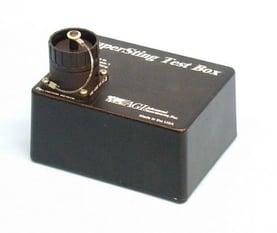
Note: The Wenner ASTM G57 tests and other single conductor wire needs were connected directly from the faceplate. The faceplate of these older machines required more cleaning and maintenance compared to the modern removable Adapter Box. Only the Test Box with Receiver Test capability was supplied at this earlier time.