To perform an automatic SP survey, you will need the following components:
- SuperSting™ R8 adapter box and grounding cable (included with the SuperSting™ R8)
- SuperSting™ R8 with firmware version 1.x3.51 or later
- Dual-mode electrodes or switch box and passive cables
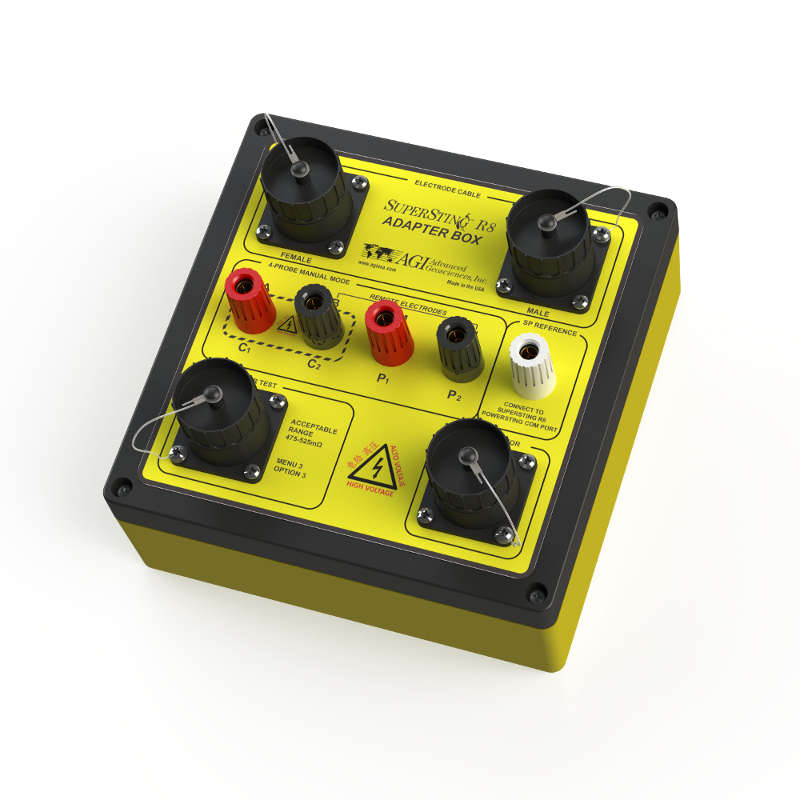
Above: The SuperSting™ R8 adapter box
The SP survey is very fast (<1 min in some cases) and sometimes runs as a single-channel measurement for this reason. You will most likely edit an automatically created command file depending on your SP measurements.
The SuperSting can do two types of SP measurements:
- Gradient SP measurements: Measure between two electrodes, moving them forward along the line while keeping their distance equal.
- SP measurements with a fixed reference: Keep one electrode in the same place while the other moves along the line and takes measurements. These readings show the difference in the potential field and the roving electrode.
Tip: The use of non-polarizable electrodes when performing an SP survey will improve the sensitivity and stability of the SP voltage measurements.
To perform an SP survey:
- Create an SP command file and load it into the SuperSting. See examples below. Keep in mind that the command file header contains information to specify which array is being used.
- Set up the equipment as seen in the diagram below

- Using a 2-meter SuperSting™ R8 Male-to-Female jumper cable, connect the SP adapter box to the SuperSting™ electrode cable connector.
- Connect the SP adapter to the switch box using another 2-meter SuperSting™ R8 Male-to-Female jumper cable.
- Connect the SP adapter box's SP reference port to the SuperSting's testing terminal using a grounding cable
- On the SuperSting's main menu, press 6, and then press 1 to get to the Measurement Settings screen.
- Change option 7 to SP.
- Continue with all other options as you would for a normal field survey, including the cable address table in menu 6.2.
- Access menu 1: Automatic Mode, and create a new data file using the SP command file you loaded earlier.
- Verify the remainder of the SuperSting™ menu settings.
- Begin taking measurements. The SP voltages are displayed on the screen.
- When measurements are complete, download the .stg file from the SuperSting™ using SuperSting™ Administrator software.
Note: When viewing the stg file, note that the column for the transmitter's current output is set to 1000mA. The column for the raw V/I value in the stg file now represents the value for V of the SP measurement.
Command File Examples
Creating a SuperSting R1 command file with the appropriate array type and number of electrodes is best when creating the SP command file. Only the command lines will need to be edited. SP surveys are relatively quick. Single-channel commands will, in most cases, take only a few minutes. The SuperSting Adapter Box SP port can measure multiple channel SP from R1, R2, R4, R6, and R8 models. In this case, you could fill in additional receiver positions to speed up the SP command files described below.
Important: The header information for the command file must indicate whether you use the wire connected to the N post or an addressed electrode as the reference. The SuperSting needs the appropriate header to be configured correctly, or the data will be inaccurate.
The following examples show the necessary headings for proper configuration.
Example 1: Header for fixed reference using N connector on SuperSting ABMN adapter (Automatically created command file)
Note: There are two different ways to approach this type of array:
- Create a pole-pole SuperSting R1 command file, and connect a wire from the reference stake to the N post on the SuperSting faceplate. This will mean that all P2 addresses in the command line section will be 0.
- Use an actual electrode on the survey line. In this case, the P2 address in the command line will be the cable's electrode address.
:header
progID=SPfixed
type=R
arraytype=5
Binf=1
Ninf=1
MUX=2
Example 2: Header for fixed reference using an addressed electrode on the survey line (Automatically created command file)
Note: The geometry section of an SP command file will be the same as the geometry section for any RES or RES/IP command file.
:header
progID=SPfixed
type=R
arraytype=3
Binf=0
Ninf=0
MUX=1
Example 3: Commands sections for fixed reference using N connector on SuperSting ABMN adapter
Note: Below are two command lines, using electrodes 1 and 2 to take measurements. Notice that A, B, and P2-P9 are all zeroes. The 1 at the end indicates that channel 1 is taking the measurement.
:commands
A,B,P1,P2,P3,P4,P5,P6,P7,P8,P9,channels
0,0,1,0,0,0,0,0,0,0,0,1
0,0,2,0,0,0,0,0,0,0,0,1
Example 4: Commands sections for fixed reference using an addressed electrode on the survey line
Note: This is using electrode 28 as the reference electrode. So A, B, and P3-P9 are still zero, but P2 now indicates that electrode 28 is the reference.
:commands
A,B,P1,P2,P3,P4,P5,P6,P7,P8,P9,channels
0,0,1,28,0,0,0,0,0,0,0,1
0,0,2,28,0,0,0,0,0,0,0,1
Example 5: Header for gradient SP (Automatically created command file)
Note: The geometry section of an SP command file will be the same as the geometry section for any RES or RES/IP command file.
:header
progID=SPgrad
type=R
arraytype=3
Binf=0
Ninf=0
MUX=1
Example 6: Commands section for gradient SP
Note: Here, the gradient measurements are taken between adjacent electrodes using P1 and P2 electrodes. Any combination of electrodes will work, so depending on what is needed, the measurement could be between electrodes 1 and 14, 2 and 6, etc.
:commands
A,B,P1,P2,P3,P4,P5,P6,P7,P8,P9,channels
0,0,1,2,0,0,0,0,0,0,0,1
0,0,2,3,0,0,0,0,0,0,0,1
Example 7: Multi-Channel SP Command File
Note: --- Here is a full 8 channel fixed reference SP measurement taken between the N post and then P1 through P9 electrodes on the main line for maximum speed. You can also reduce the channels to fit a SuperSting R1, R2, R4, R6 or R8 WiFi. The geometry section needs to contain all 28 electrode ID's to be a proper SP command file.
Sample Command File: Download
;SP with remote fixed reference electrode on N post with M potentials switched in full 8 channels
:header
progID=SPFX28R8
type=R
arraytype=5
Binf=1
Ninf=1
MUX=2
:geometry
1,0.00,0.00
2,1.00,0.00
3,2.00,0.00
.
Continue this pattern
.
27,26.00,0.00
28,27.00,0.00
28,27.00,0.00
:commands
;A,B,P1,P2,P3,P4,P5,P6,P7,P8,P9,channels
0,0,1,2,3,4,5,6,7,8,0,12345678
0,0,8,9,10,11,12,13,14,15,0,12345678
0,0,15,16,17,18,19,20,21,22,0,12345678
0,0,22,23,24,25,26,27,28,0,0,1234567