Follow the steps below to perform the FOP method (IEEE Std 81) using the SuperSting™.
Important Notes:
- The MiniSting™ can send out a maximum of 0.5 Amp and is suitable for many grounding systems. For large grounding grids, where the profile line is longer, performing the FOP method with the SuperSting™ instrument is a better choice because it can send out up to 2 Amp and has a more advanced and sensitive receiver.
- Before performing the survey, it is important to disconnect the grounding grid or grounding stake from the apparatus or structure to be protected by the grounding system. This is to prevent the test instrument current from splitting between other connected parallel grounding systems, equipment, structures to be protected, etc..
To perform the FOP method using the SuperSting™:
Setup your Survey Area:
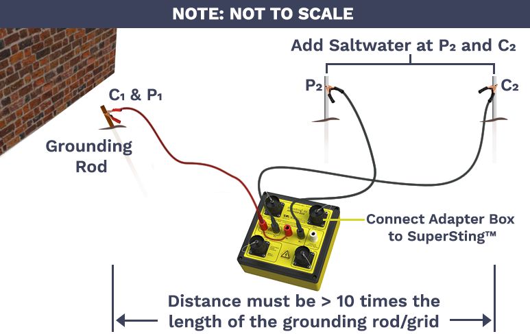
Figure 1: Connect C1 and P1 (shorted together at the SuperSting™ Adapter Box) to the connection point of the grounding rod, connect the C2 wire to the return current electrode and connect the P2 wire to the probing electrode. (See Figure 3 & Figure 4 for detailed view)
The fall-of-potential method involves passing an electrical current through the grounding system electrode (C1 and P1), and at the same time measuring the electrical potential between the grounding system and a “probing” electrode (P2).
The return current electrode C2 is placed at a large distance from the grounding system, in line with the grounding system and the P2 electrode.
The size of the grounding grid determines the length of the survey line. As a rule of thumb, if a grounding rod is used, the return current electrode C2 should be away from the grounding rod at least 10 times the length of the ground rod. If a grounding grid is used, the return current electrode C2 should be placed at least 10 times the size of the largest diagonal of the grid, away from the grounding grid.
Setup your SuperSting™:
1. Power the SuperSting™ with isolated marine deep cycle battery (NEVER use a car battery. It can damage the instrument and cause noise)
2. Turn on the SuperSting™ and note that the battery voltage is at least 12 (See Figure 2 - The voltage is 12.29V). Replace the battery if it is below 11.7V
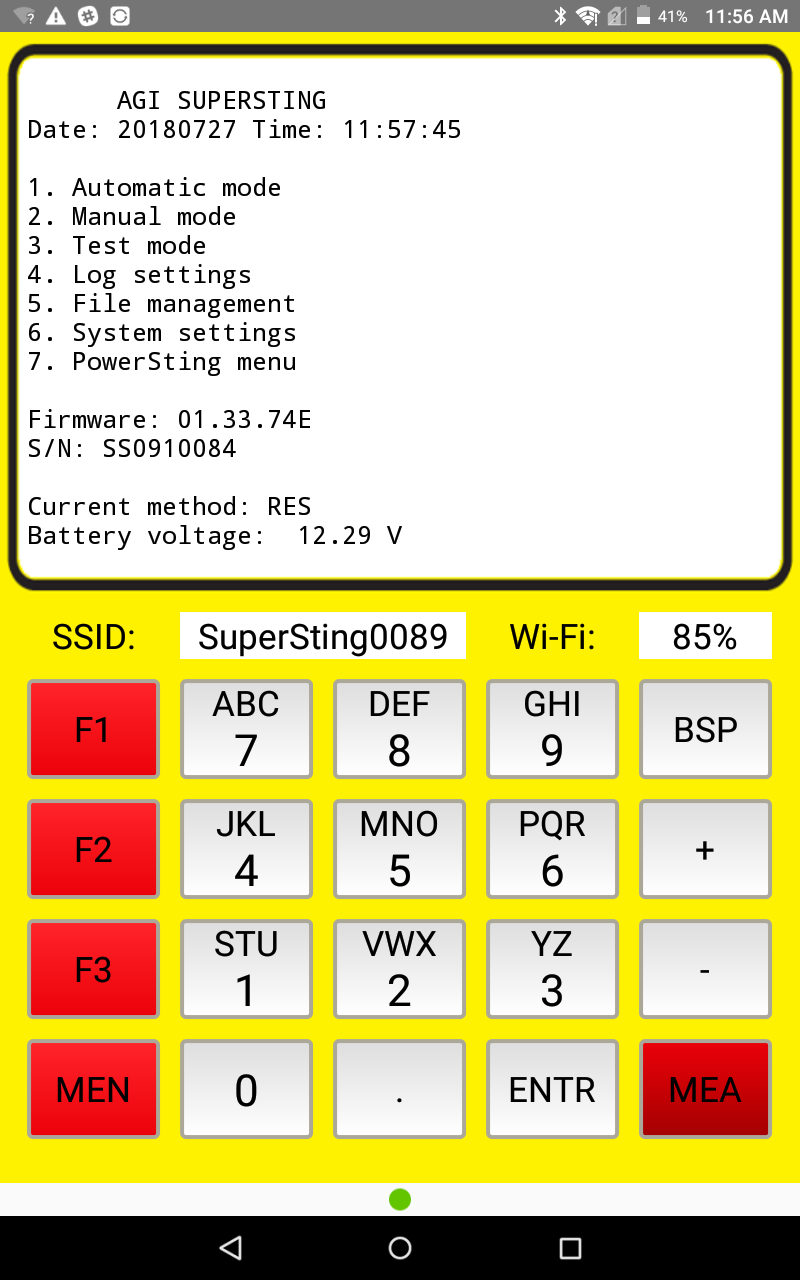
Figure 2: SuperSting™ Wifi main menu
3. Press 2 on the keypad to enter Manual Mode, then press 1 to enter Resistance Mode.
4. Press 2 to create a data file, then enter a name.
5. Select what unit of measurement you want to use (meters or feet)
6. Connect the SuperSting™ Adapter Box with a short yellow jumper cable to either of the upper ports to either matching male or female ports on the SuperSting™. See Figure 3 or Figure 4 below (NOTE: On older SuperSting™ units, use the connectors mounted directly on the faceplate)
7. Connect and prepare FOP wires/electrodes for C1, C2, P1, and P2. You may use the setup shown in Figure 3 or Figure 4 below.
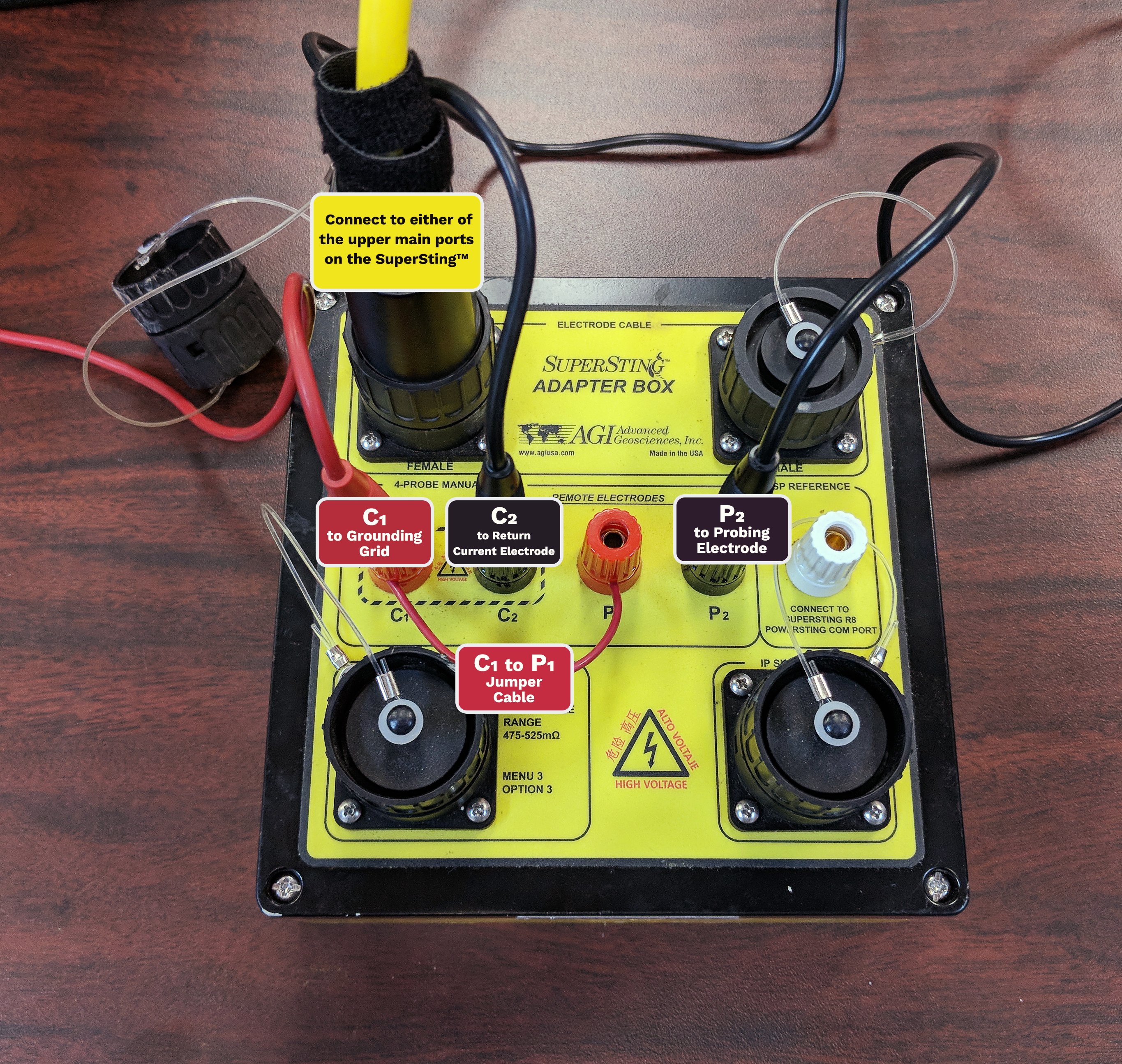
Figure 3: Terminals C1 and P1 are shorted at the terminals using a short piece of wire. The C1 wire goes to the grounding grid connection point, the C2 wire goes to the return current electrode and the P2 wire goes to the probing electrode.
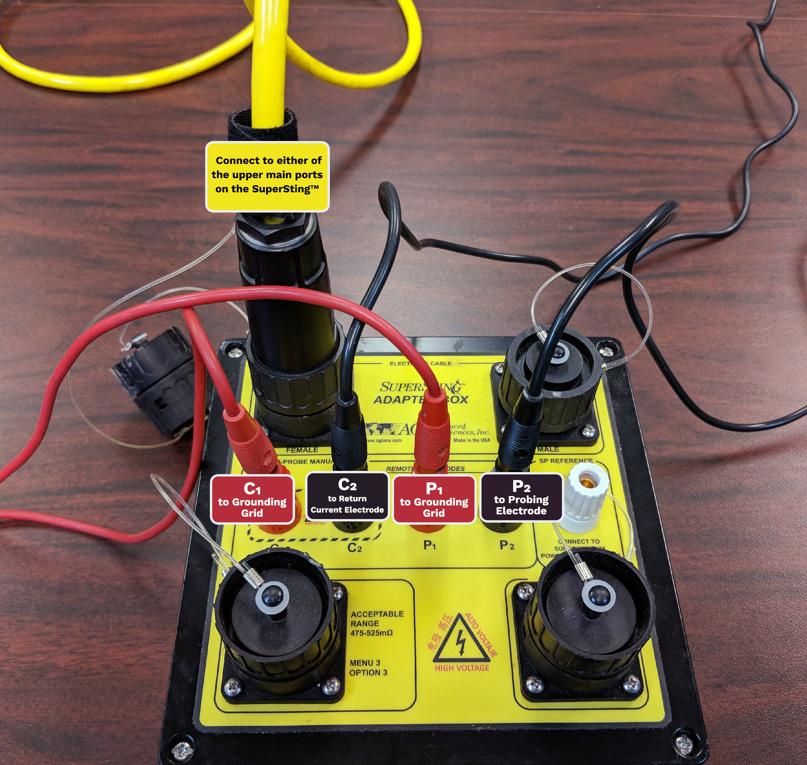
Figure 4: The C1 and P1 wire connects to the electrode grounding connection point. The C2 wire goes to the return current electrode and the P2 wire goes to the probing electrode.
Perform your survey:
- Be sure that you've set up your survey as illustrated in Figure 1.
- Wet the ground around electrodes P2 and C2 with a little bit of saltwater (2% salt by volume and 1/2 quart is sufficient) to improve the contact to the ground. DO NOT wet the grounding rod/grid as this could temporarily alter the grounding of the structure of interest.
- Press MEA to measure and link to a table with positions of the electrodes (See Figure 5 for an example)
- Leave X & Y=0 and log positions externally using the Record# to link later if need be after download. We suggest storing all FOP data in 1 file for convenience and noting the record#. This same file can be used on multiple days and the system can be powered off as needed.
IMPORTANT: Make sure that all electric power to the equipment and structures is disconnected before disconnecting the grounding system.
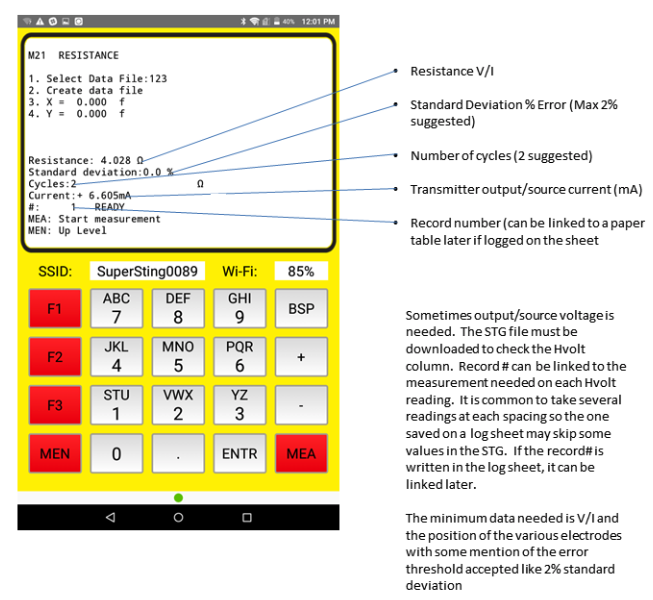
Figure 5: SuperSting™ R1 resistance mode reading Example