Follow the steps below to perform the FOP method (IEEE Std 81) using the MiniSting™
Important Notes:
- The MiniSting™ can send out a maximum of 0.5 Amp and is suitable for many grounding systems. For large grounding grids, where the profile line is longer, performing the FOP method with the SuperSting™ instrument is a better choice because it can send out up to 2 Amp.
- Before performing the survey, it is important to disconnect the grounding grid or grounding stake from the apparatus or structure to be protected by the grounding system. This is to prevent the test instrument current from splitting between other connected parallel grounding systems, equipment, structures to be protected, etc..
To perform the FOP method using the MiniSting™:
Setup your Survey Area:
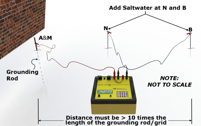
Figure 1: Connect A and M (shorted together at the instrument) to the connection point of the grounding rod, connect the B wire to the return current electrode and connect the N wire to the probing electrode.
The fall-of-potential method involves passing an electrical current through the grounding system electrode (A and M), and at the same time measuring the electrical potential between the grounding system and a “probing” electrode (N).
The return current electrode B is placed at a large distance from the grounding system, in line with the grounding system and the N electrode.
The size of the grounding grid determines the length of the survey line. As a rule of thumb, if a grounding rod is used, the return current electrode B should be away from the grounding rod at least 10 times the length of the ground rod. If a grounding grid is used, the return current electrode B should be placed at least 10 times the size of the largest diagonal of the grid, away from the grounding grid.
Configure your MiniSting™:
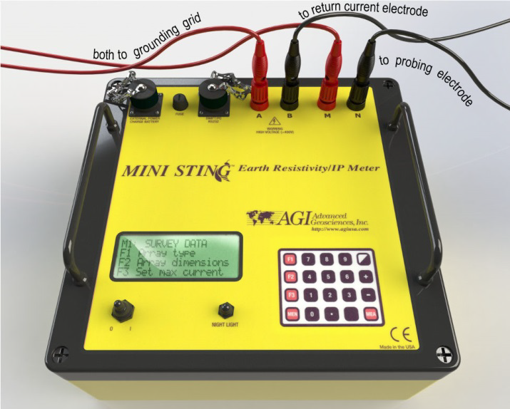
Figure 2: The A and M wire connects to the electrode grounding connection point. The B wire goes to the return current electrode and the N wire goes to the probing electrode.

Figure 3: Terminals A and M are shorted at the terminals using a short piece of wire. The A wire goes to the grounding grid connection point, the B wire goes to the return current electrode and the N wire goes to the probing electrode.
- Attach the instrument to the electrode grid connection point. You may use the setup shown in Figure 2 or Figure 3.
- Set a few parameters (These will stay the same for the whole survey):
- Turn the MiniSting™ on and press the number 1 key to get to menu 1.
- Press F1 and press the + or – key to scroll to “Resistance.”
- Press MEN to get back to menu 1.
- Press F3 and use the + or – keys to select a suitable current, for example, 50 mA.
- Press MEN to get back to menu 1.
- Press the number 2 key to get to menu 2.
- Press F1, select 2 cycles, and then press MEN.
- Press F2, select 2%, and then press MEN.
- Press F3 followed by F1 to select a unit for coordinates (Usually feet in the U.S)
- Press F2 a number of times until 3.6 sec is displayed. Press MEN to get back to menu 2.
- Press the number 3 key to get to menu 3. Press F3 and then F1, and finally the (.) dot key to erase the memory from previously recorded data. Make sure that all important data in memory are downloaded to a computer prior to erasing the memory. Press MEN to get back to menu 3.
- Press the number 4 key to get to menu 4. Press F1 to set date and time. Press MEN to get back to menu 4.
- Press the number 6 key to get to menu 6. Press F1 and make sure the Swift mode is turned off. Press MEN to get back to menu 6.
Perform your survey:
- Be sure that you've set up your survey as illustrated in Figure 1.
- Wet the ground around electrodes N and B with a little bit of saltwater (2% salt by volume and 1/2 quart is sufficient) to improve the contact to the ground. DO NOT wet the grounding rod/grid as this could temporarily alter the grounding of the structure of interest.
- On the MiniSting™, press 1 to get to menu 1, and then press F2 to enter the first Resistance coordinates for the probing electrode. Zero is typically the grounding grid connection point. The Y-coordinate stays 0 for the whole survey since you are measuring on a straight line. When the coordinate is entered by pressing F3, the display is automatically changed back to menu 1. The instrument is ready for measurement.
- Press the MEA key to start the measurement cycle. Measured data is automatically stored in the memory and can later be downloaded to a computer using the “Stingdump” download module of the Administrator software.
- After the first reading is taken, move the probing electrode to the next location.
- Repeat step 2 above to enter the new X-coordinate and then start a new measurement by pressing MEA.
- A sufficient number of measurements should be taken, evenly spread between the grounding electrode and the return current electrode B to be able to plot a resistance versus distance graph of the measurements. Typically ten (10) measurements, evenly distributed between the grounding electrode and the return electrode B, are sufficient to create a suitable plot.
- Measurement data is displayed on the screen and can be copied to a field protocol. Data is also stored in the internal memory and can be downloaded to a computer after the survey. The data format is: Record number, RESIST, date, time, V/I, error in tenths of a percent, output current in mA, X-coordinate for the probing electrode, Y-coordinate for the probing electrode.
- Plot the V/I (resistance) versus the X-coordinate to evaluate the data:
- The result V/I should be plotted against the distance from the electrode grounding point. The curve should show a flat spot along the middle of the curve; this flat line is horizontally extended to the Y-axis (see Figure 4 below). The intersection between this horizontal line and the Y-axis gives the ground resistance value for the grounding system. If a horizontal line is not achieved in the plot, the return current electrode has probably been placed too close to the grounding electrode point. Try moving the return current electrode further out about 50% more and repeat the measurements.
IMPORTANT: Make sure that all electric power to the equipment and structures is disconnected before disconnecting the grounding system.
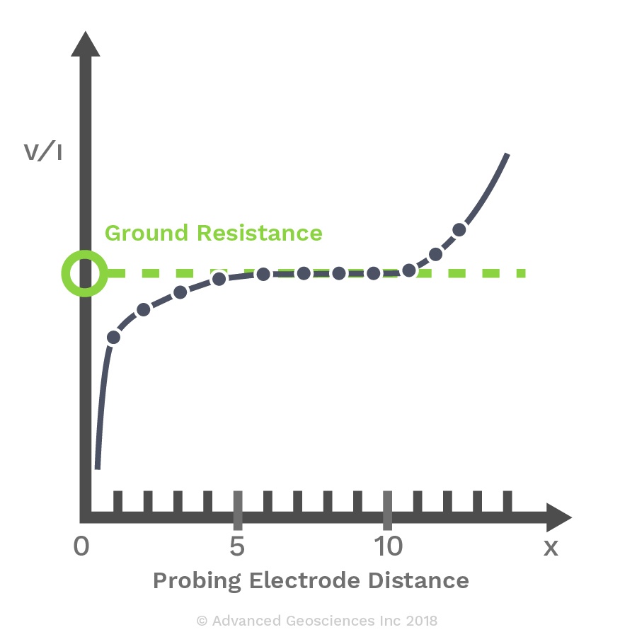
Figure 4: Resistance ( V/I ) plotted against probing electrode distance from the grounding grid connection point.